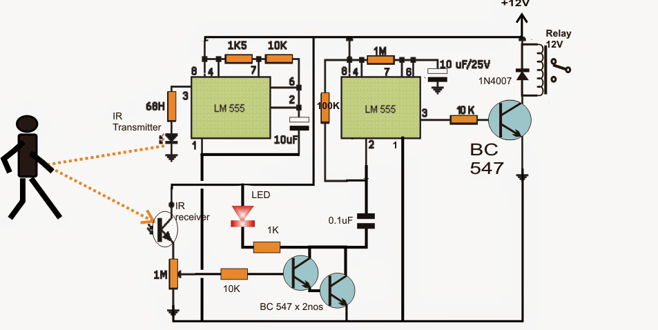
7-Segment Counter Circuit. This timer circuit is wired as an astable multivibrator to display a seven. Circuit of this IR detector is given below: When the IR Sensor Circuit is switched ON, IR LED starts emitting the Infrared, which falls upon the photodiode and a potential difference is generated across PHOTO diode which Turns On the transistor BC547, which further Turns On the Transistor BC557 by pulling down its base to Ground. Now Transistor BC557 starts conducting and power supply is applied to the 555 Timer IC (at PIN 8), which turns ON the 555 IC.
- Ir Transmitter Receiver Circuit Using 555 Timer
- Ir Receiver Circuit Using 555
- Ir Circuit Using 555 Arduino
- Ir Circuit Using 555 Circuit
- Ir Transmitter Circuit With 555
- Ir Receiver Circuit Using 555 Timer
Ir Transmitter Receiver Circuit Using 555 Timer

Need to design a simple and useful security alarm then you can refer this IR Based security Alarm using 555 timer prototype. In this circuit IR (Infra Red) beam acts as a Invisible fence, whenever the IR Rays are blocked then this circuit will produce alert sound through loud speaker.
This circuit has two stage, first one is IR emitter & IR receiver stage then second one is Astable Multivibrator timer circuit, Here the timer circuit Reset pin is Accessed by the IR stage hence the multivibrator oscillates when the IR rays blocked.
Circuit Diagram
Components Required


- IR LED Photo diode pair
- IC 555
- Loud speaker 8Ω
- Resistors 220Ω, 10KΩ, 1KΩ, 150KΩ each one
- Variable Resistor 10KΩ
- LED green
- Capacitors 0.1μF = 2, 0.01μF
- Transistor BC547
- Battery 9V
Construction & Working
Ir Receiver Circuit Using 555
Here IC 555 timer is configured in Astable multivibrator mode and Reset pin is connected with Q1 transistor collector terminal, this Q1 transistor acts as a switch and connects the Reset pin to Ground if the IR rays received by photo diode and connects with positive supply if there IR rays blocked.
Ir Circuit Using 555 Arduino

Ir Circuit Using 555 Circuit
The IR LED gives IR rays continuously and it should be placed towards photo diode in straight line.
Ir Transmitter Circuit With 555
Here the timer IC output frequency is depends on the timer Resistor R4, VR1 and timer capacitor C2, by varying VR1 we can get different level output sound at loud speaker.
Ir Receiver Circuit Using 555 Timer
